Since the seminal work of Ashkin on radiation pressure,
the possibility to exploit the mechanical action of
optical fields to trap and manipulate neutral particles has
spawned a wide range of applications. From atomic and
non linear physics to biology, optical forces have provided
a convenient way to control the dynamics of small particles.
In this web page we present a brief overview of our research in optical forces.
For more details on each topic have a look at the references.
Time averaged total force on a minute sphere
Optical tweezers: selective nanomanipulation (movie)
Optical binding (movie)
Optical trapping near a photonic crystal
Optical force on magnetic and negative-index scatterers
Optical force in time domain (movie)
Optical force on a Discrete Invisibility Cloak in
Time-Dependent Fields (movie)
Optical binding of magnetodielectric Rayleigh particles
Time averaged total force on a minute sphere
At optical frequencies involved in many experiments only the time
average of the electromagnetic force is observed. We establish the
form of the time averaged total force on a particle smaller that the
wavelength of illumination without restriction on the spatial
dependence of the electromagnetic field. The i-th component of the
time averaged optical force can be written, with the help of the value of the field at the location of the minute particle, as:
| Fi= |
| Re | ⎛ ⎝ | α Ej ∂i Ej* | ⎞ ⎠ |
where * denotes the complex conjugate and i and j stand for the
component either x, y,z. α is the polarizability of the minute
particle: Clausius-Mossotti formula with the addition of radiation
reaction as we have shown that the radiation reaction term must be
accounted for, in order to derive the correct expression for the total
optical force.
Reference:
- P. C. Chaumet and M. Nieto-Vesperinas,
Time averaged total force on a dipolar sphere in an electromagnetic field, Opt. Lett. 25, 1065 (2000). pdf
Optical tweezers: selective nanomanipulation
Optical tweezers have proved useful not only for trapping particles but also
for assembling objects ranging from microspheres to biological
cells. However, most of these manipulations
involve particles whose size is between one and several
micrometers. While for much smaller particles, such as
atoms or molecules, the scanning tunneling microscope
provides a powerful tool for manipulation and engineering; dealing with neutral particles of a few nanometers requires new experimental approaches.
In 2002 we propose an experimental scheme to selectively
capture and manipulate nanoparticles in vacuum
or air above a substrate, using the tungsten probe of an
apertureless near-field microscope (see image below). The particles are not
in a liquid environment, hence there is no Brownian motion
and the apertureless probe can be used as a near-field optical probe to localize and select the particles. This is an important asset when different particles have to be placed according to a specific pattern or when interactions between particles are investigated.
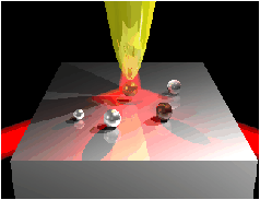
For TM illumination there is a large enhancement of the field near
the apex of the probe. As a consequence, when the tip approaches the sphere, the sphere is attracted by the tip due to the gradient force. On the other hand, for TE polarization the optical force remains negative
(directed toward the substrate and away from the tip) as the
tip gets closer to the particle. This prevents any trapping.
As shown by the movie (start the movie by placing your cursor on the image, if it does not work click here) the procedure to trap a small object with a tungsten tip is therefore the following: TE illumination is used while the
tip scans the surface in tapping mode or in constant-height
mode if the area under investigation is small enough. Such
modes avoid the displacement of the particle by the tip.
Once an object has been selected, the probe is placed above
the object and the polarization of the illumination is rotated
to TM. The probe is then brought down over the particle
and captures it. The probe can then move the particle
above the substrate, both horizontally and vertically, to a
new position where it can be released by switching back to
TE polarization.
References:
- P. C. Chaumet, A. Rahmani, and M. Nieto-Vesperinas,
Selective nanomanipulation using optical forces,
Phys. Rev. B 66, 195405 (2002). pdf - P. C. Chaumet, A. Rahmani, and M. Nieto-Vesperinas,
Optical trapping and manipulation of nano-object with an apertureless probe,
Phys. Rev. Lett. 88, 123601 (2002). pdf
Optical fields can induce forces between microscopic objects, thus giving rise to different structures of
matter. Then we have studied the forces induced by light between two
spheres, either isolated in solution, or in the presence of a flat
dielectric surface. We shall monitor the nature, either attractive
or repulsive, of the light induced force between the
spheres, according to the wavelength, polarization of the incident
wave, and size and composition of the spheres.
For example for two small (compare to the wavelength of illumination λ) spheres A and B in free space, the scattering force is negligible
and thus only the gradient force remains, due to the interaction
between the dipole associated with sphere B, and to the
variation of the field created by sphere A at the position of
sphere B. Then following the phase relationship between
the dipole associated with sphere B and the field due to sphere A, the force is
either positive or negative on sphere B; hence, the oscillations of the
force take place with period λ. The movie (start the movie by placing your cursor on the image, if it does not work click here) below shows the force experienced by sphere B (arrow in green) versus the distance between the two spheres, the sphere A remains fixed. We have plotted with red arrows the equilibrium positions spaced out by one wavelength.

References:
- P. C. Chaumet, and M. Nieto-Vesperinas,
Optical binding of particles with or without the presence of a flat dielectric surface., Phys. Rev. B 64, 035422 (2001). pdf
Optical trapping near a photonic crystal
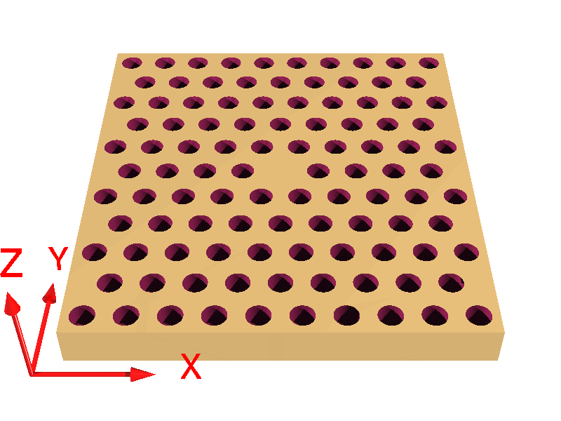
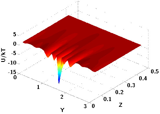
We have showed that the photonic confinement induced by a photonic
crystal can be exploited to trap nanoparticles: total internal reflection and multiple scattering in a photonic crystals slab
structures can be combined to confine photons very efficiently. A consequence of this confinement is the existence of strong gradients of electromagnetic intensity in the near-field of the photonic structure. Hence, a nanoparticle placed in the vicinity of the crystal would experience an optical force which, with a proper design of the near-field optical landscape, can lead to trapping.
|
|
|---|---|
| Schematic of the finite photonic crystal microcavity used in the computation | Vertical dependence of the optical trapping potential U for a nanoparticle in a plane located at height z above the cavity, as a function of the lateral position of the particle along direction x. All distances are normalized to λ, the resonance wavelength of the cavity. |
Reference:
- A. Rahmani and P.C. Chaumet, Optical Trapping near a Photonic Crystal,
Opt. Express 14, 6353 (2006). pdf
Optical force on magnetic and negative-index scatterers
We have recently presented a general derivation of the electromagnetic
force and torque, in the case of a dipolar object with arbitrary dielectric permittivity ε and magnetic permeability μ. We then described how these results can be incorporated into a more general coupled dipole method approach to find the electromagnetic force and torque experienced by an arbitrary object (beyond the dipole approximation). The present approach
can be used to extend the study of the opto-mechanical coupling between light and matter to magnetic and meta-materials. For example we have studied the case where the scatterer has material parameters ε =μ = −1,
i.e, a negative index of refraction.
We also studied the optical binding of electrically small magnetodielectric particles.
References:
- K. Jay, P. C. Chaumet, T. N. Langtry, A. Rahmani, Optical binding of electrically small magnetodielectric particles, J. Nanophotonics 4, 041565 (2010). pdf
- P. C. Chaumet, A. Rahmani,
Coupled-dipole method for magnetic and negative refraction materials,
J. Quant. Spec. Rad. Trans. 110, 22 (2009). pdf - P. C. Chaumet, A. Rahmani,
Electromagnetic force and torque on magnetic and negative-index scatterers, Opt. Express. 17, 2224 (2009). pdf
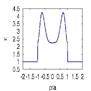
We have recently presented a time-domain formulation of electrodynamics
based on the self-consistent derivation of the electromagnetic field in a
linear, dispersive, lossy object via the coupled dipole method.
For example consider an inhomogeneous sphere with a radius
a, a relative permittivity profile given by: ε(ρ) = 2.25+2sin2(πρ2/a2) where ρ is the distance between the center of the sphere and a point inside the sphere. The profile of the relative permittivity versus ρ is ploted in the figure located on the right side.
The incident field is an electromagnetic pulse with a Gaussian envelop and a spectrum centered on frequency f0=c/λ0
with λ0=1.25 a. t0=8/f0 is the duration of the pulse.
The incident field is a plane wave with linear polarization propagating towards the right side of the figure.
As shown by the movie (start the movie by placing your cursor on the figure showing the relative permittivity profile, if it does not work click here) the field close to the surface of the sphere the telltale of a creeping wave can be observed (successive bursts in the amplitude of the field at the left and right side of the sphere after the sequence of the incident wave). This particular wave propagates along the surface of the sphere and the interval between successive bursts corresponds to the time it takes the wave to travel around the sphere.
The figure below shows (a) the optical force experienced by the particle plotted versus the time in the presence of a creeping wave and (b) the momentum imparted by the pulse to the object. We have separated the force into two parts. The first part Fh is the standard term that appears in the time-harmonic treatment of optical forces, while the second part Fp is a term that vanishes in a time-harmonic picture
and which has seldom been considered in the treatment of optical
forces on complex objects. We have the total force Ft=Fh+Fp.
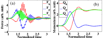
We observe that the force remains non-zero long after the incident pulse has passed over the object. This is a consequence of the excitation, by the incident pulse, of creeping waves at the surface of the sphere. Accordingly, the force, and to a lesser extent the momentum, exhibit weak oscillations at the optical frequency 2f0 and stronger oscillations at a frequency corresponding to the reciprocal of the period of the creeping wave
(time required for the wave to travel around the sphere).
References:
- P. C. Chaumet, K. Belkebir and A. Rahmani, Optical Forces in Time Domain on Arbitrary Objects, Phys. Rev. A. 81, 021803(R) (2010). pdf
- P. C. Chaumet, K. Belkebir and A. Rahmani, Coupled-dipole method in time domain, Opt. Express. 16, 20157 (2008). pdf
Optical force on a Discrete Invisibility Cloak in
Time-Dependent Fields

We study, in time domain, the exchange of momentum between an
electromagnetic pulse and a three dimensional, discrete, spherical
invisibility cloak. We find that a discrete cloak, initially at
rest, would experience an electromagnetic force due to the pulse but
would acquire zero net momentum and net displacement. On the other
and, we find that while the cloak may manage to conceal an object
and shroud it from the electromagnetic forces associated with the
pulse, the cloak itself can experience optomechanical stress on a
scale much larger than the object would in the absence of the cloak.
We also consider the effects of material dispersion and losses on
the electromagnetic forces experienced by the cloak and show that
they lead to a transfer of momentum from the pulse to the cloak.
The figure on the right shows (a) Optical force experienced by the cloak
versus time and its different contributions. (b) Momentum of the
cloak versus time and its different contribution. (c) Position
multiplied by the mass of the cloak of the center of mass of the
cloak versus time.(d) Spectrum of the EM force and of its different
contribution.
 width="350" height="347" alt="" title="" align="right" hspace="10" vspace="5" border="10" onmouseout="this.src='/spip/IMG/gif/forcetfort-2.gif'" width="350" height="347" alt="Nano-manipulation avec une pointe apertureless" title="" align="right" hspace="10" vspace="5" border="10">
We can visualize how the force is distributed at the time tA (see figure above) within the cloak by plotting (arrows in the right figure) the density of electromagnetic force inside the cloak. In fact the mechanical stress on the cloak can be stronger than the stress that the object to be protected
would experience in the absence of the cloak. Obviously, this is
more likely to be an issue for mechanical waves (acoustic waves,
pressure and shear waves,...) for which similar cloaking
approaches exist.
On the same figure we also plot the energy
density as a color scale. Figure highlights the energy build-up near the outer boundary of the cloak.
The movie started by placing your cursor on the image (if it does not work click here) shows the
energy density as a color scale and the optical force experienced by the cloak with a black arrow versus time. The length of the arrow is proportional to the magnitude of the optical force.
Reference:
- P. C. Chaumet, A. Rahmani, F. Zolla, A. Nicolet and K. Belkebir
Optical force on a Discrete Invisibility Cloak in Time-Dependent Fields, Phys. Rev. A 84, 033808 (2011). pdf
Optical binding of magnetodielectric Rayleigh particles
We have studied theoretically and numerically the optical binding and optical torque between two Rayleigh particles with arbitrary, complex, scalar dielectric permittivity and magnetic permeability. We have used a computational approach based on the discrete dipole approximation to derive the optical force and torque experienced by
the particles when illuminated by a linearly or circularly polarized plane wave.
We have particularly showed that two magnetodielectic particles experience a long-range optical torque whose amplitude envelop does not decay with the separation between the particles when ε=µ and illuminated with a circular illumination, see blue line in right figure. This is due to the 1/a spatial dependence of the y component of the optical force, see blue line in left figure.

Reference:
- P. C. Chaumet, A. Rahmani, Optical binding of magnetodielectric Rayleigh particles, Phys. Rev. B 87, 195125 (2013). pdf


 ResearchGate
 Flux RSS