|
Abstract
|
|||
| A dedicated set up is built to obtain localized transmittance and reflectance spectral measurements. The spatial resolution ranges from 50 µm up to 2 mm and the spectral resolution is about 5 nm. This apparatus can be used to study the index and thickness uniformity on single layers in order to determine and optimize the characteristics of the deposition chamber. It can also be used to measure the optical characteristics of intended non uniform coatings such as linear variable filters | |||
| A dedicated set up is built to obtain localized transmittance and reflectance spectral measurements. The spatial resolution ranges from 50 µm up to 2 mm and the spectral resolution is about 5 nm. This apparatus can be used to study the index and thickness uniformity on single layers in order to determine and optimize the characteristics of the deposition chamber. It can also be used to measure the optical characteristics of intended non uniform coatings such as linear variable filters | |||
![]()
|
Introduction
|
||
|
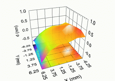
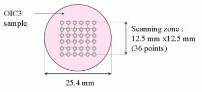
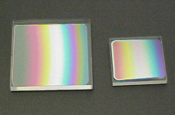
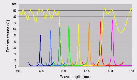
Transmittance and reflectance spectrophotometric measurements are frequently used to control the optical properties of multilayer coatings or to perform a thickness and refractive index characterization on single layers. Most often, such measurements are made with a light beam diameter of several millimeters, which results in a spatial average value for the measured properties. However, for some applications, localized measurements over a much smaller diameter may be required, especially when the deposited thickness must be accurately controlled all over the surface of the components. This is the case for DWDM filters, for which the highest thickness uniformity is expected over the component diameter which is about 1 mm. Localized measurements can therefore be helpful to characterize and optimize the optical thickness distribution of the deposition chamber. As an opposite example, intended thickness gradients are used for manufacturing linear variable filters. In that case, localized measurements are then required to characterize the optical properties of the components, the thickness gradient and the geometry of iso-thickness lines |
||
![]()
|
Description of the spectrophotometer
|
||
|
PRINCIPLE : The system is illuminated by a fibered white light source and spectrophotometric measurements are performed with an Optical Spectrum Analyser. The principle of the apparatus consists in forming the image of a calibrated aperture stop on the sample in order to define a small probing zone. For this purpose, the entrance fiber is imaged on the aperture wheel with a magnification equal to 10. The aperture wheel is imaged on the sample with a unit magnification. At last, the sample is imaged on the exit fiber with a magnification equal to 1/10. Telecentric objectives are used all along the light path so that the incoming light can be entirely collected by the exit fibers. Fiber core diameters are progressively increased to allow greater positioning tolerances. The reflectance or transmittance channel is selected by a mirror translation so that optical fiber never need to be disconnected. |
||
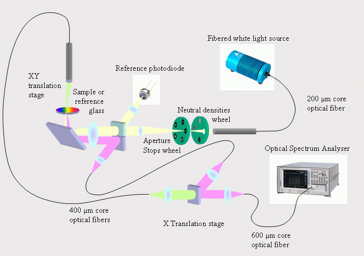
|
NUMERICAL DATA : Available apertures stops Ø : 50, 100, 200, 600, 1000 and 2000 µm. Sample positioning accuracy : 3 µm Beam divergence ≈ 1.25° Angle of incidence ≈ 2.8° Light source: Quartz-halogen. Optical Spectrum Analyser : Ando AQ 6315A
A reference photodiode is used to correct power fluctuations. Stability standard deviation (light source + OSA) ≈ 10-4 The standard deviation of measurement repeatability ≈ 10-3 (including positioning and measurement of both the reference glass and the sample.) Acquisition time from 400 to 1700 nm ≈ 1 s for a 2 mm analysis Ø ≈ 360 s for a 50 µm Ø Data acquisition and sample positioning are completely computer controlled. |
|